Airport shuttle bus
I was the engineering lead for an airport shuttle bus project, with a total of 16 buses delivered to Swissport for use at major airports around Australia. Within the team, I compiled customer requirements, led design reviews, and maintained the Bill of Materials used by our procurement and operations teams. Where possible, I supported our mechanical engineers to enable timely completion of the design phase.
Most of my time was divided between that design work, managing documentation, and ensuring the procurement and workshop teams had everything they needed to build the buses to spec. Once parts started arriving and buses neared completion, I also took on quality control inspections of incoming parts and completed buses.
Specifications and other documents that I devoted a lot of time to can’t be shared here. However, I can highlight some areas where I contributed (and those are also readily observed by anyone taking a trip to the airport).
Pre-sales support
In the year leading up to contract finalisation, I provided pre-sales support to Nexport’s commercial team and met with the customer on several occassions to work out their needs and finalise technical specifications.
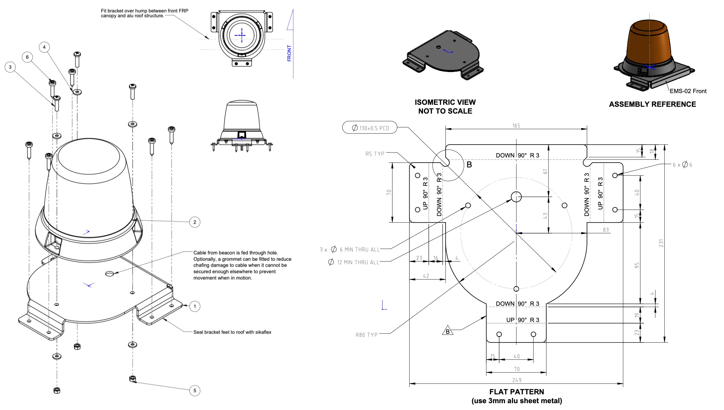
Rooftop beacons lights
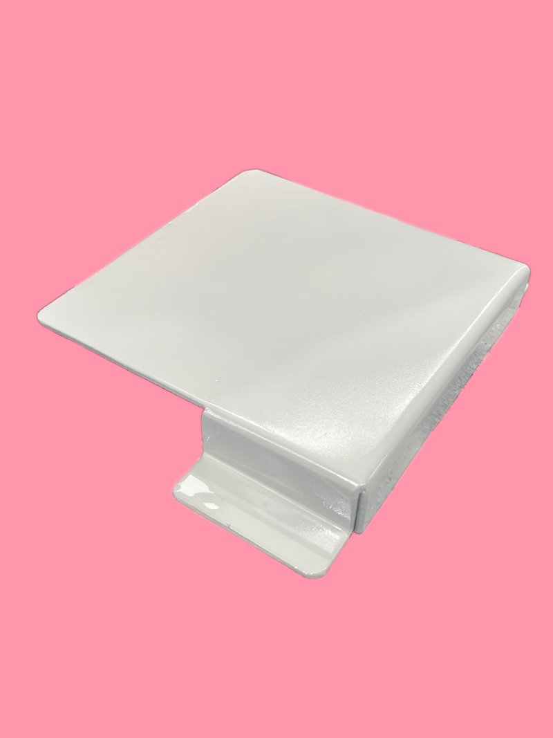
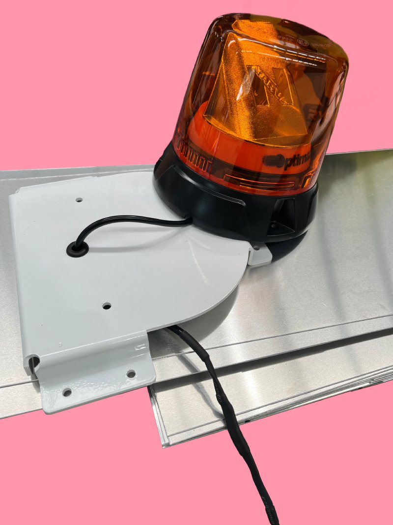
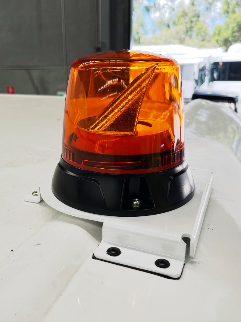
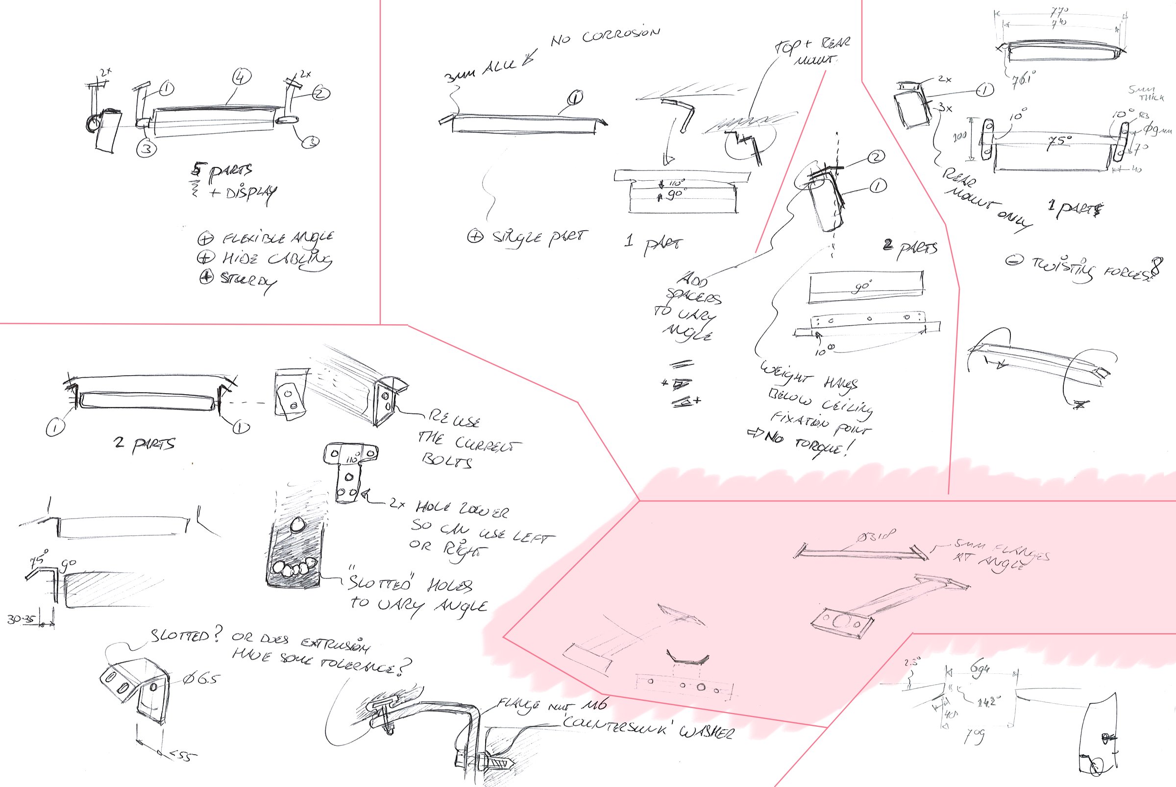
Because these buses have to abide by airport-specific regulations, I specified fitting a set of rooftop beacon lights near the front and rear. We could not fit the front beacon directly to the roof due to a bump in that area, so our production supervisor requested an additional bracket to be designed. I took that as an opportunity to hone my sheet metal design skills in SolidWorks.
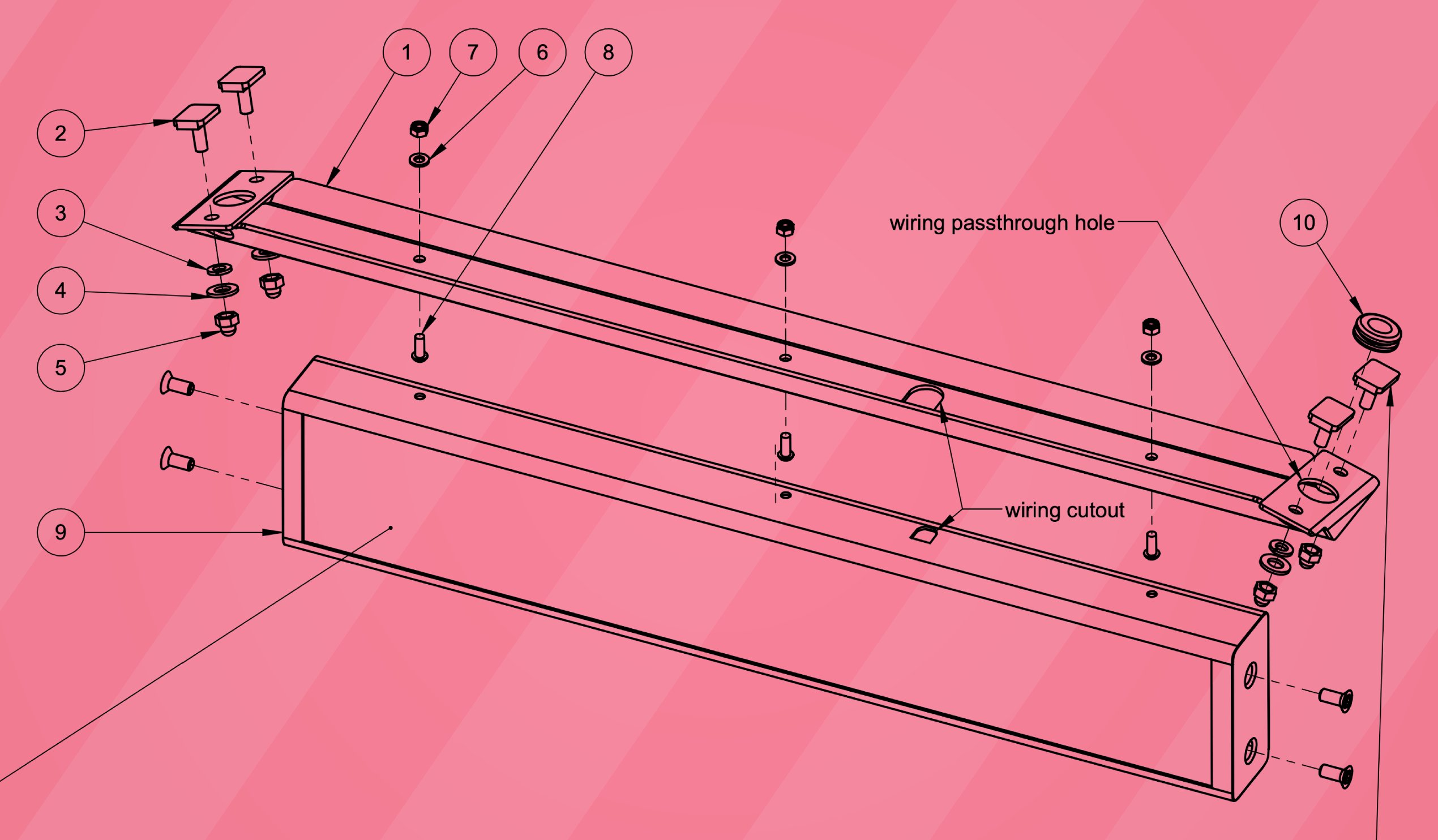
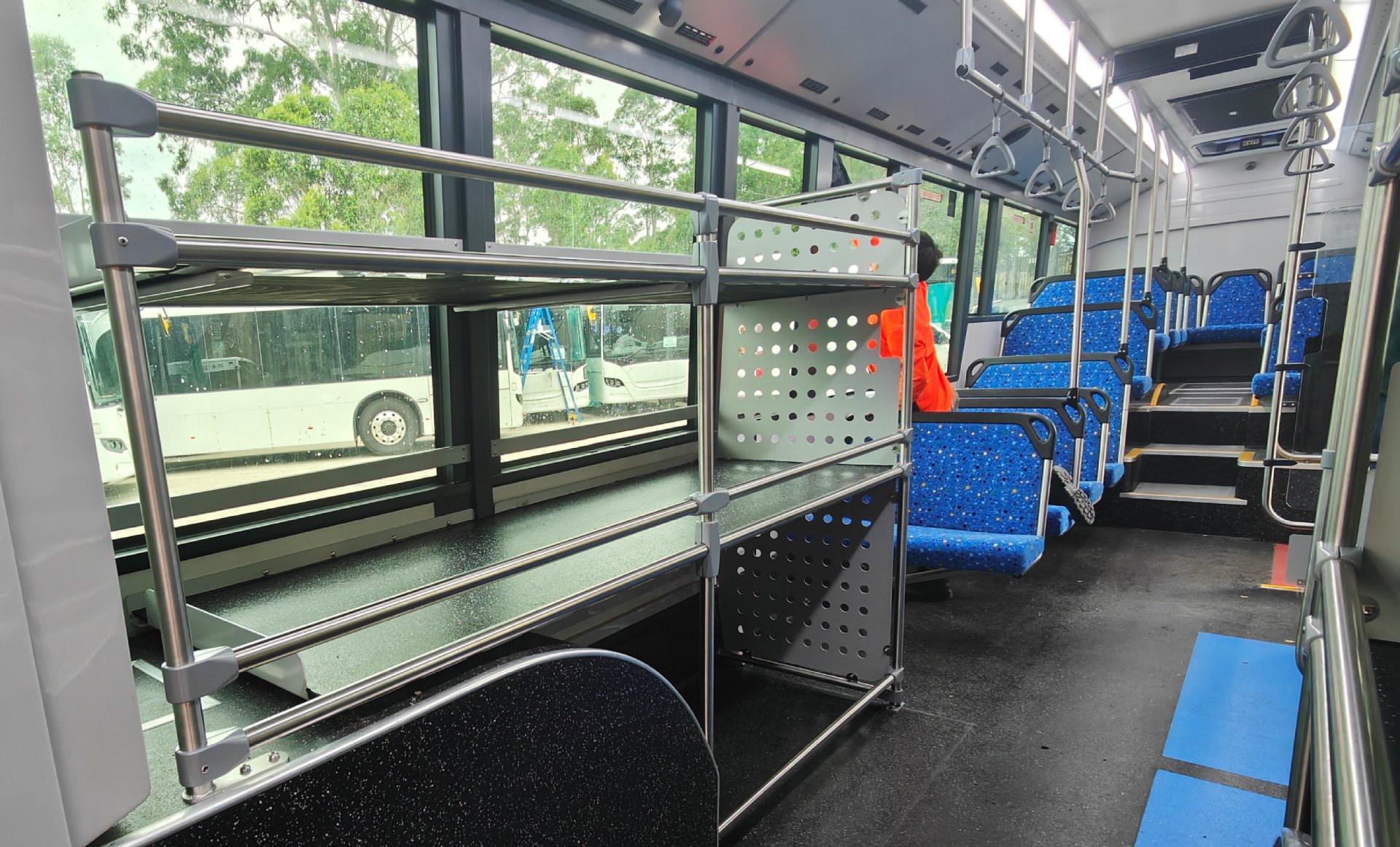
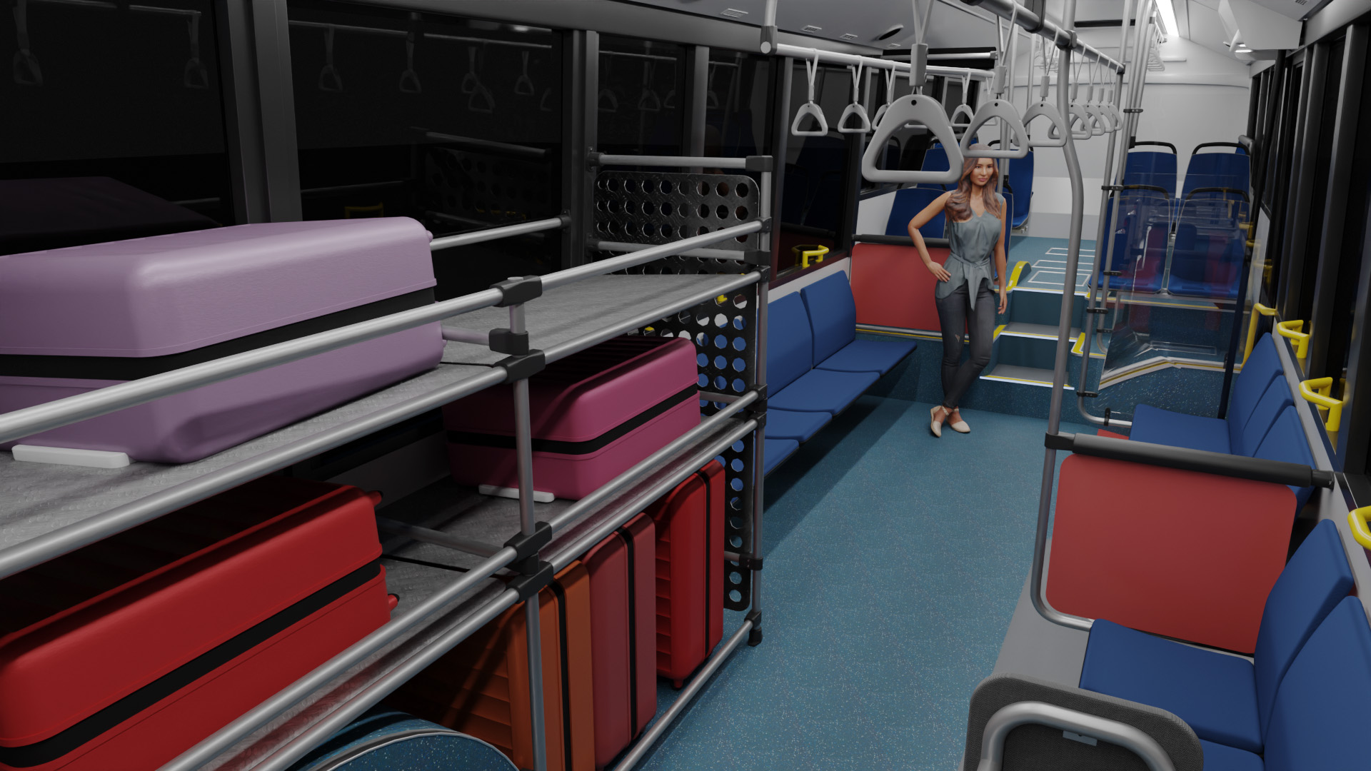
Interior passenger information system
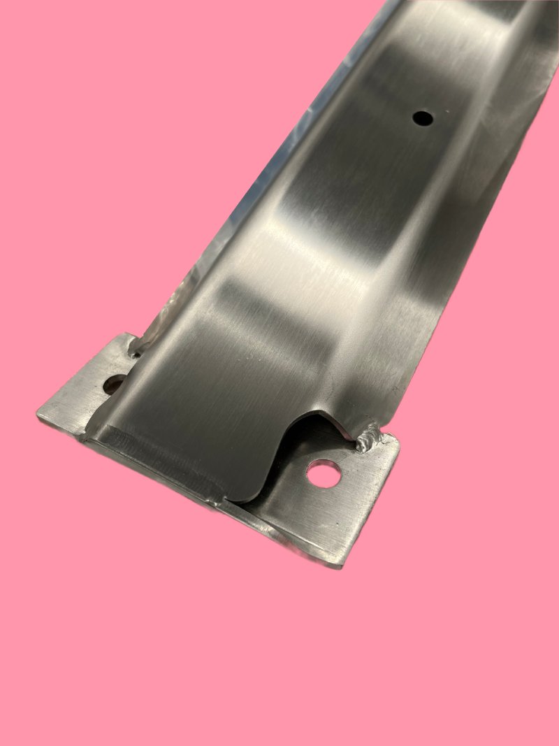
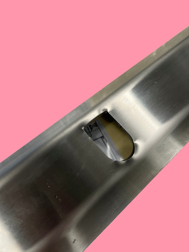
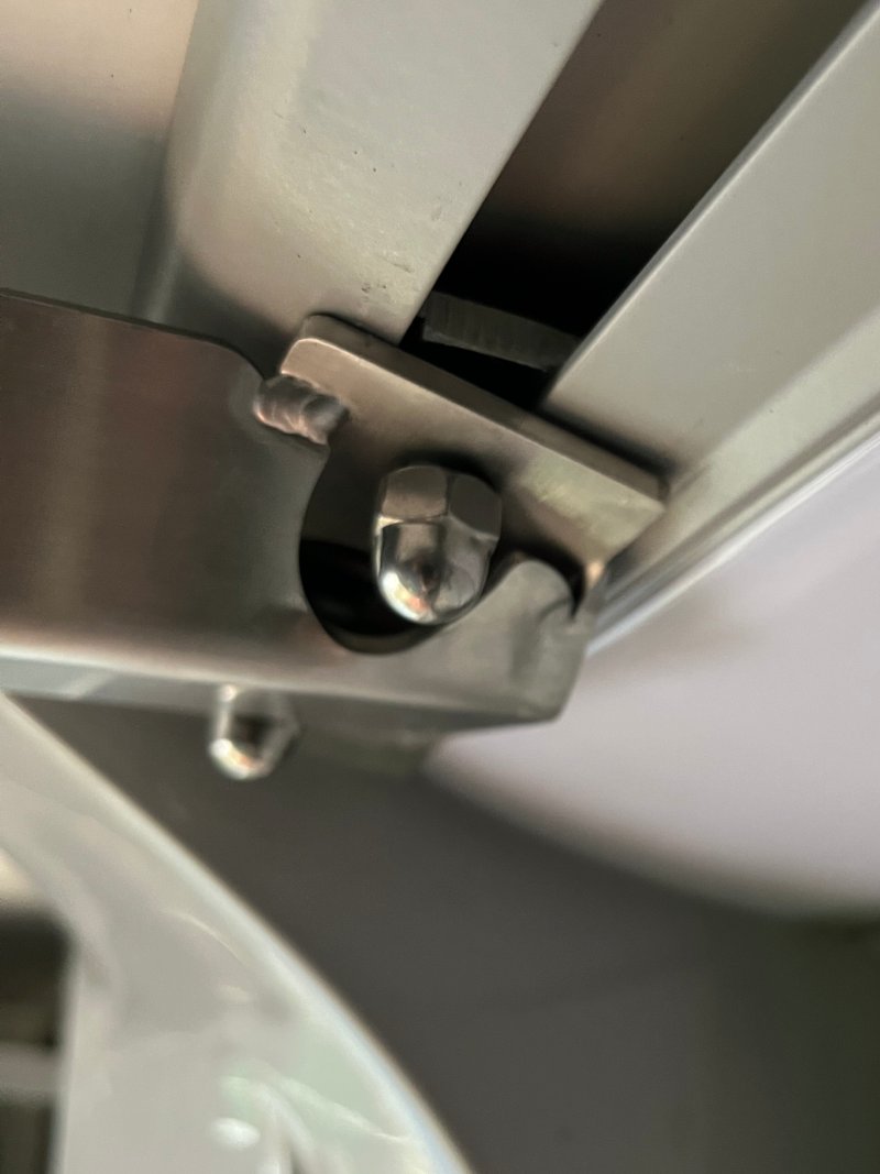
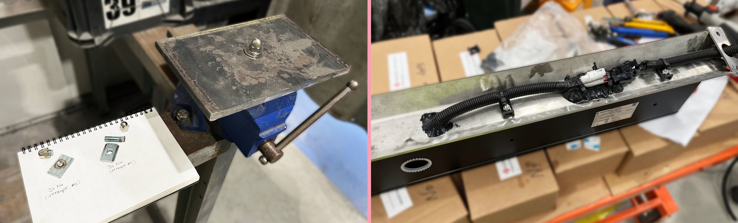
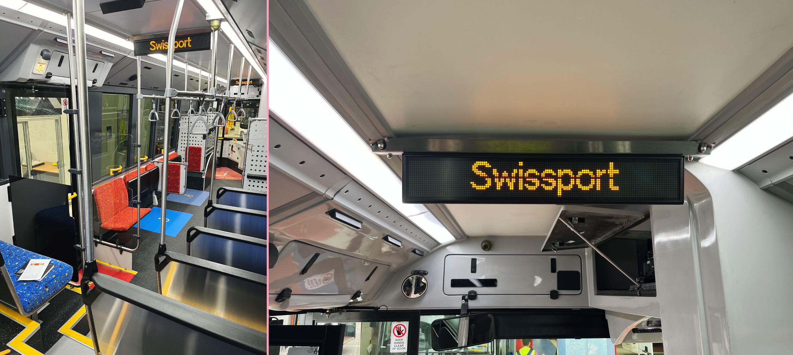
Our customer required an internal passenger information system that would show the next stop and announce this over the speaker system. I worked with the system supplier to get a suitable configuration within the allotted budget. This left me with the question of mounting the two interior displays. My intention was to design a simple bracket that would allow the displays to fit over the aisle without exposing its cabling or otherwise intrude into passengers’ headspace. I also wanted to stick to materials and finishes we already used for other components made by our supplier.
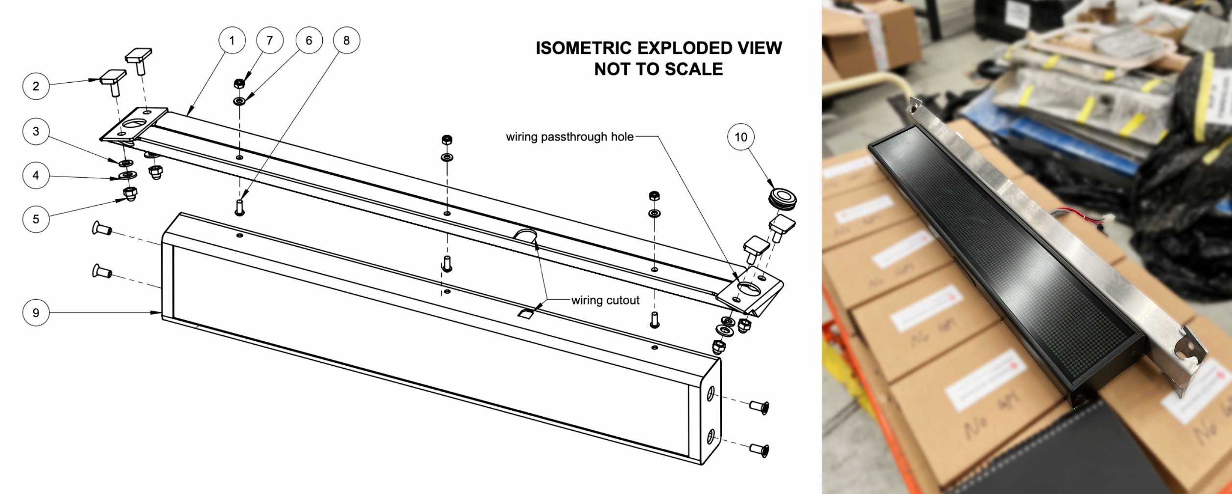
As part of the design process, I checked that the first fabricated part matched my drawings and was suited for its eventual purpose. I also made sure it could be assembled and installed without major concerns, and documented the right procedure for QA/QC purposes. After an early test fit, I worked with production staff to fit all cabling in and determined the easiest way to put it all together.
Outcomes and reflection
This project proved quite the challenge for two reasons. First, time available to design and revise was limited because of tight delivery deadlines. Second, as an organisation we had some ways to go in developing efficient ways of converting a design proposal into a built product, with significant effort required in taking the engineering design and turning it into a Bill of Materials that was easily understood internally and by suppliers. With limited established systems, processes, and templates, I in particular had to cover quite some ground getting the info right for other departments. It proved a very valuable lesson though, highlighting clear areas for improvement.